Project Portfolio

Stuff I Build For Fun


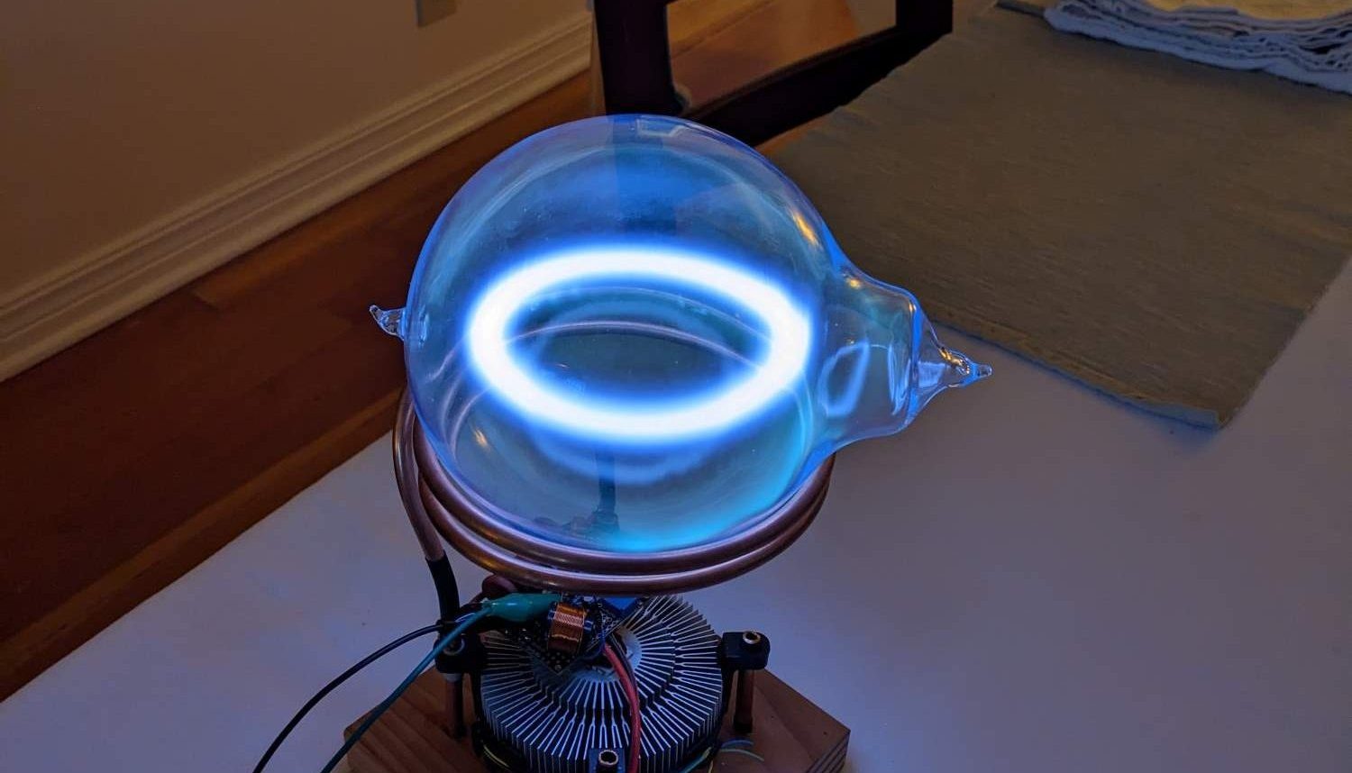
Plasma Toroid Generator


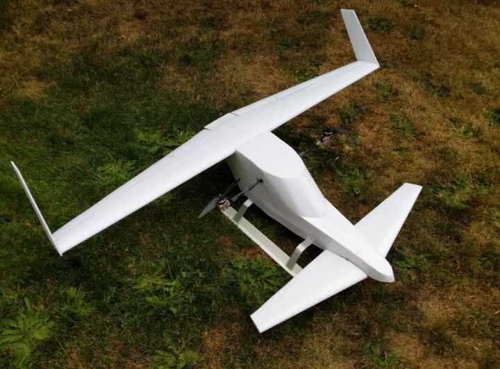
Bicopter

Freewing Canard Concept Development


Acoustic Reflection Fish Tracking

Developing miniaturized acoustic based fish ID tags. Acoustic reflectors offer more efficient transmission in water(and thus smaller hardware), enabling the tagging of smaller and younger fish. The Washington fish and wildlife service is explicitly interested tracking young Salmon but cannot do so due to size constraints of RFID tags.

Pictured at left is a range-finding prototype using off the shelf piezos.


1.2 Million Volt Tesla Coil

(more to come)


Colibri eVTOL

The culmination of many years designing and building RC aircraft

Design Documentation

Motivation

The eVTOL(Electric Vertical Take off and Landing) concept been the subject of increasing popularity in recent years. Improvements to battery and motor technology have pushed the electrification of small passenger aircraft into the realm of practicality. Inherent advantages of electric propulsion are being leveraged to design entirely new kinds of aircraft. Many startups hope to carve out their own niche, fulfilling the popular desire for flying cars with short range intercity multirotors. Other, more ambitious ventures hope to provide long rang public transportation with hyper-efficient fixed wing concepts that can transition seamlessly between horizontal and vertical flight. These hybrids are posed to revolutionize transportation, competing directly with combustion fueled counterparts. The engineering challenges involved with creating this kind of jack-of-all-trades aircraft have produced a fascinating diversity of concepts. From Joby’s tilt-rotor hexacopter to Lilium’s ducted fan approach, there’s no shortage of startups pursuing this style of regional transport. But can their range be extended even farther? In the search for sustainable alternatives, how can we replace combustion-fueled interstate travel? Can electric propulsion power long-range transportation while still leveraging it’s aptitude for VTOL capabilities?

Goals

-Design an original concept for an interstate eVTOL aircraft

-Build a reasonably sized 1-2m foamboard airframe

-Build a powertrain using readily available quadcopter and model airplane electronics

-Use an Arduino and original code to achieve smooth transitions between flight modes and active stabilization in hover

-achieve 20 mins of flight time with at least 2 mins of vertical flight on a 2100 mah 4s LiPo battery

Design Summary

Airframe

To achieve both horizontal and vertical flight I will use a tilt-rotor fixed wing layout. A fixed wing is a necessity for range as it offers the most efficient means of lift. The wing will feature a high aspect ratio and a roughly elliptical lift distribution. Both of these features are universal considerations maximizing the lift to drag ratio of a wing. To simplify the building process, the wing will have a mildly tapered trailing edge. When combined with a couple degrees of washout at the wingtips, the overall lift distribution will be nearly elliptical. This will change as the airplane approaches a stall. The washout will ensure that the center of the wing stalls first, allowing for a more gradual stall that preserves aileron authority longer.

To accommodate the tilt-rotors, the airframe will use an unconventional forward stabilizer as a canard. This differs from notable tilt-rotors like the V-22. The V-22 mounts tilt-rotors on either end of its wingtips. While this allows a more typical airframe, it adds considerable weight at the largest possible distance from the cg, and likely looses some lift in hover due to interference with the wing. The cg of a canard layout is naturally ahead of the leading edge, allowing for propellers and motors that are not only closer to the cg, but that also blow over a greater portion of the wing while in horizontal flight. This lends to the possibility of accelerated airflow over the wing at slow speeds, extending the flight envelope of the aircraft. Ultimately this allows for a smaller wing that produces less excess lift/drag while at higher speeds.

To accommodate the tilt-rotors, the airframe will use an unconventional forward stabilizer as a canard. This differs from notable tilt-rotors like the V-22. The V-22 mounts tilt-rotors on either end of its wingtips. While this allows a more typical airframe, it adds considerable weight at the largest possible distance from the cg, and likely looses some lift in hover due to interference with the wing. The cg of a canard layout is naturally ahead of the leading edge, allowing for propellers and motors that are not only closer to the cg, but that also blow over a greater portion of the wing while in horizontal flight. This lends to the possibility of accelerated airflow over the wing at slow speeds, extending the flight envelope of the aircraft. Ultimately this allows for a smaller wing that produces less excess lift/drag while at higher speeds.

It’s important to note that the V-22 suffers from problems inherent to tilt-rotors. It can neither effectively auto-rotate nor glide particularly well. This has contributed to the fatality of a number of crashes involving power loss. To avoid the hazards of associated with being neither a good helicopter nor airplane, my eVTOL concept will lean heavily towards fixed wing flight. Despite an undersized wing, safety necessitates slow speed flight and reasonable glide characteristics in the case of power failure. The wing uses a full length elevon in normal flight, but when transitioning, the canard will assume pitch control, allowing the elevon to deflect downwards as a flaperon. This intermediary flight mode offers a lower stall speed and increased drag, allowing for a slow speed horizontal landing in an emergency situation.

(note: the canard uses the same airfoil profile as the wing, so it is swept back to ensure it always stalls first)

This design decision eliminates the need for autorotation and collective pitch control. Additionally, the propellers will forgo any cyclic pitch control, lending themselves to the simplified layout of an electric powertrain. The same mechanism that tilts the rotors forward will control pitch in hover.

(Discussed further in software section)

Disk loading is another tricky aspect of tilt-rotors. Helicopters place more demand on their rotors than those of an airplane propeller. To lower disk loading helicopters use large rotor blades. The problem becomes obvious when those blades must be tilted forward. The V-22 uses propellers that are as large as practicality allows, but this limits tip velocity, resulting in a slow cruise speed and inefficient, low-aspect ratio blades.

Fortunately efficiency in hover is of relatively little concern for a point to point transporter. Lilium recognized this with their regional eVTOL. They utilize 36 small lift fans for propulsion and lift, disregarding high disk loading in hover. This level of aerodynamic complexity is sure to cause some loss of efficiency in horizontal flight however. Ducted fans have the potential to improve efficiency by reducing tip losses, but this is typically given a similar diameter to a comparable propeller. As numerous as they are, Lilium’s fans have relatively little combined area compared to possible open-rotor design. Lilium’s angle on ducted fans includes quiet operation, a factor that again becomes less of a consideration with longer, higher-altitude flights and short hovers. My concept will utilize a pair of of high aspect ratio bi-propellers optimized for horizontal flight, sacrificing high disk loading and excessive blade pitch in hover.

Electronics

When selecting electronics for an RC aircraft I start with the battery. It characterizes the general weight and power of the aircraft. I’ll be using a 4s 2100mah Lithium Polymer battery. At 20mins of flight time this should allow somewhere around a 1/20th scale demonstrator. For an RC plane of this size I would typically use a three cell battery, but an extra 4.2 volts will be needed to hover. A pair of high performance race quad BLDC motors will spin the props. I choose the 2806.5 Avenger 1300Kv motors paired with an APC 8×4.5 Bi-Blade 8″. At 14.8v a 1300Kv will spin at around 19,000 rpm. Of course this is given no resistance which isn’t particularly useful. A look at the manufacturer’s load testing shows that at 24v and a 7×3.5 tri blade, the motor spins at about 2/3 of its theoretical Kv.

Manufacturer data on Motor

With only 14.8v and only a slightly more draggy prop, 2/3 should be a conservative estimate of the RPM I can expect. This is equal to 12,826rpm. Below is an excerpt from the manufacturer’s performance data on the propeller at 12000rpm. This indicates the aircraft will produce at least 4.5 pounds of thrust in a static hover. Given a margin for roll authority with differential thrust, this gives me a maximum possible weight for the total airframe. With a 2100mah battery I should be able to achieve a 20min flight time at an average of less than 40% throttle. 2100mAh/4.6A= .46 hours = 27.4 mins. Given that most of the flight (horizontal) will use significantly less throttle than what’s needed to hover, this should be achievable.

 8x4.5MR                  (8x45MR.dat)                                 12/25/14                       
                                                                                                              
                                                                                                              
         ====== PERFORMANCE DATA (versus advance ratio and MPH) ======                                        
                                                                                                              
         DEFINITIONS:                                                                                         
         J=V/nD (advance ratio)                                                                               
         Ct=T/(rho * n**2 * D**4) (thrust coef.)                                                              
         Cp=P/(rho * n**3 * D**5) (power coef.)                                                               
         Pe=Ct*J/Cp (efficiency)                                                                              
         V  (model speed in MPH)                                                                              

 PROP RPM =      12000                                                                                
                                                                                                              
         V          J           Pe         Ct          Cp          PWR         Torque      Thrust             
       (mph)     (Adv Ratio)                                       (Hp)        (In-Lbf)     (Lbf)             
         0.0        0.00      0.0000      0.1215      0.0494       0.225       1.181       2.283              
         2.5        0.03      0.0669      0.1207      0.0503       0.229       1.204       2.267              
         5.1        0.06      0.1302      0.1197      0.0513       0.234       1.227       2.249              
         7.6        0.08      0.1900      0.1186      0.0522       0.238       1.249       2.228              
        10.1        0.11      0.2465      0.1173      0.0531       0.242       1.270       2.204              
        12.7        0.14      0.2997      0.1158      0.0539       0.245       1.289       2.176              
        15.2        0.17      0.3498      0.1141      0.0546       0.249       1.305       2.143              
        17.7        0.20      0.3968      0.1121      0.0551       0.251       1.319       2.106              
        20.3        0.22      0.4410      0.1098      0.0555       0.253       1.328       2.062              
        22.8        0.25      0.4825      0.1070      0.0557       0.254       1.331       2.010              
        25.3        0.28      0.5214      0.1038      0.0555       0.253       1.328       1.950              
        27.9        0.31      0.5578      0.1002      0.0551       0.251       1.318       1.883              
        30.4        0.33      0.5915      0.0962      0.0544       0.248       1.302       1.808              
        33.0        0.36      0.6228      0.0920      0.0535       0.244       1.281       1.728              
        35.5        0.39      0.6518      0.0873      0.0523       0.238       1.252       1.641              
        38.0        0.42      0.6783      0.0825      0.0509       0.232       1.217       1.550              
        40.6        0.45      0.7023      0.0775      0.0492       0.224       1.178       1.456              
        43.1        0.47      0.7238      0.0724      0.0474       0.216       1.134       1.359              
        45.6        0.50      0.7430      0.0669      0.0452       0.206       1.081       1.257              
        48.2        0.53      0.7591      0.0613      0.0428       0.195       1.024       1.152              
        50.7        0.56      0.7725      0.0556      0.0401       0.183       0.960       1.044              
        53.2        0.59      0.7828      0.0497      0.0372       0.169       0.890       0.934              
        55.8        0.61      0.7886      0.0438      0.0341       0.155       0.815       0.823              
        58.3        0.64      0.7899      0.0377      0.0306       0.140       0.733       0.709              
        60.8        0.67      0.7853      0.0316      0.0269       0.123       0.644       0.594              
        63.4        0.70      0.7704      0.0254      0.0230       0.105       0.550       0.477              
        65.9        0.72      0.7366      0.0191      0.0188       0.086       0.450       0.359              
        68.4        0.75      0.6645      0.0129      0.0146       0.066       0.349       0.242              
        71.0        0.78      0.4869      0.0065      0.0104       0.047       0.249       0.122              
        73.5        0.81     -0.0019      0.0000      0.0065       0.029       0.155       0.000             
                                                                                                              

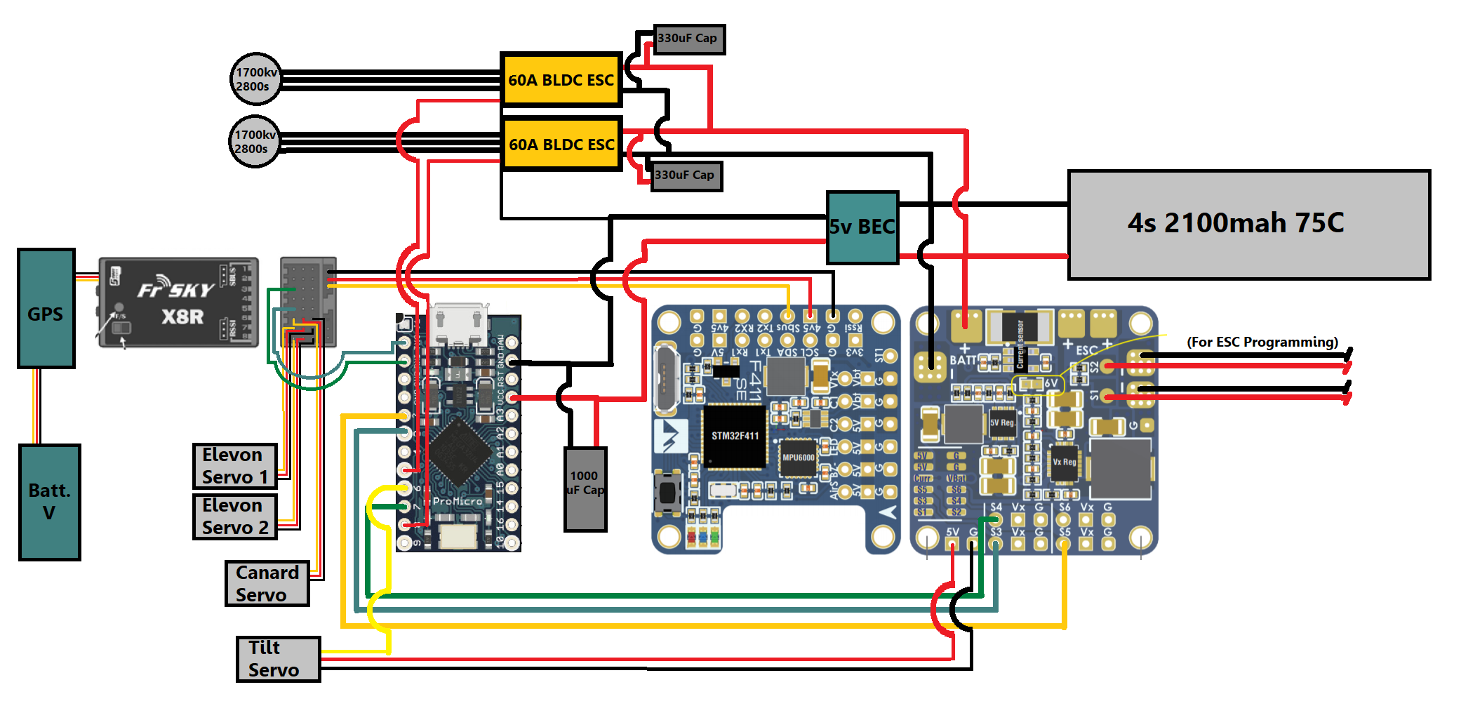
Power from the battery will be split between electronic speed controllers(ESCs) for the motors, a flight controller board, and a 5v BEC. The ESCs run an open source software called BL Heli. This is critical because I will be signaling the ESCs with raw PWM signal from the Arduino. Typically the ESC signal is bidirectional. This allows for RPM filtering with a standard flight controller. Without RPM filtering BL Heli allows me to tune the ESC for my specific motors. I wont go too much into motor tuning methodology because it’s widely applicable to quadcopters and nothing unique on this project. The motors spun best with a slightly higher timing angle (around 18 deg) and with medium demag compensation.

The flight controller (FC) allows access to the ESCs with it’s USB port. Most critically the FC also provides gyro data to the Arduino for the pitch and roll axis. It has a built in BEC as well, but with this many 5v outputs it wont be able to handle everything, hence the dedicated BEC. All the control surfaces will be handled by the receiver. It’s possible to drive the servos using the flight controller or the Arduino directly, but the receiver offers the most direct means of control. Its the “dumbest” electrical component, so if anything goes wrong with software in the Arduino or FC, I’ll still be able to glide to the ground. The RX also relays GPS and Battery telemetry to the transmitter.

Code

#include "PWM.hpp"
#include <Servo.h>
#include <Wire.h>
 

//output variables for motors and tilt
int leftmotor;
int rightmotor;
int tiltOUT;

//input variables from FC
int throttle;
int roll;
int pitch;
int yaw;
int tiltIN;

//intermediate variables for transitioning
int rollMIX;
int yawMIX;
int pitchMIX;


//Outputs
Servo leftmotoroutput; 
Servo rightmotoroutput; 
Servo tiltoutput;

//pins in
PWM ch1(0);
PWM ch2(2);
PWM ch3(3);
PWM ch4(7);
PWM ch5(1);


void setup () {
  
  ch1.begin(true);
  ch2.begin(true);
  ch3.begin(true);
  ch4.begin(true);
  ch5.begin(true);   
  //Output Pins
  leftmotoroutput.attach(5);   // throttleleft
  rightmotoroutput.attach(9);  // throttleright
  tiltoutput.attach(6);      // tiltservo
}

void loop () {

  //making math easier  for mixing(setting the midpoint to zero)
    if (ch1.getValue() > 1000 && ch1.getValue() < 2000) {
    throttle = ch1.getValue() - 1500;
  } else {
    throttle = -500;
  }
  
  tiltIN = ch5.getValue() - 1500;  
  roll = ch2.getValue() - 1500;
  pitch = ch3.getValue() - 1500;
  yaw = ch4.getValue() - 1500;
  
   
  //transitions
  tiltIN = constrain(tiltIN, -500, 500);
  //reduces roll and pitch as motors tilt forward, while introducing yaw
  rollMIX = roll * (1 - ((tiltIN + 500) * 0.001));
  yawMIX = yaw * ((tiltIN + 500) * 0.001);
  pitchMIX = pitch * (1 - ((tiltIN + 500) * 0.001));
  //adding the axis together for throttle values
  leftmotor = throttle + (rollMIX * 0.2) - (yawMIX * 0.2) + 1500;
  rightmotor = throttle - (rollMIX * 0.2) + (yawMIX * 0.2) + 1500;
  tiltOUT = - tiltIN - pitchMIX + 1500;
  //PWM ranges
  tiltOUT = constrain(tiltOUT, 1200, 1800);
  leftmotor = constrain(leftmotor, 1000, 2000);
  rightmotor = constrain(rightmotor, 1000, 2000);
  //outputs
  tiltoutput.writeMicroseconds(tiltOUT);
  leftmotoroutput.writeMicroseconds(leftmotor);
  rightmotoroutput.writeMicroseconds(rightmotor);
  
  delay(30);
}

This code switches between inputs as the rotors transition. While hovering differential thrust is used for stabilized roll and the tilt servo for stabilized pitch. As the blades pitch forward the combined PID and control input from these axis is reduced. Simultaneously, yaw input replaces roll input in differential thrust. The yaw has no PID stabilization as the aircraft is passively stable with its vertical stabilizers. The transmitter itself has a simple Lua script that temporarily raises the angle of incidence of the canard during transitions.

Small changes in the angle of the rotors induces pitch

Without active stabilization, a hovering multirotor has neutral static stability. It may fly for a few seconds but it will be nearly impossible to keep in the air, let alone go where the pilot wants. Active stabilization assists the pilot. I will be implementing a basic control loop, known as a PID loop. A PID loop has proportional, integral and differential components. Each part is a “loop” meaning it continually reacts to inputs that are influenced by its own outputs as well as outside disturbances and pilot inputs. A PID loop will be assigned to the pitch and roll axis. Below is the bare-bones equation:

//basic PID math
unsigned long past;
double kp, ki, kd;
double In, Out, Setpoint;
double errorSum, pastError;

void Compute()
{
   unsigned long now = millis();
   double timeChange = (double)(now - past);
   double error = Setpoint - In;
   errorSum += (error * timeChange);
   double dErr = (error - pastError) / timeChange;
   Out = kp * error + ki * errorSum + kd * dErr;  
   pastError = error;
   past = now;
}

The purpose of the PID loop is to continually output an error value, in this case the difference between a given setpoint(or pilot input) and data from the gyro. The proportional term looks at the angle of the aircraft in a given axis, allowing for motor inputs that move the aircraft towards the setpoint. The derivative term looks at angular velocity. This allows for dampening of angular momentum. As the P term moves the aircraft towards the setpoint, the D term will grow stronger in opposition, eliminating oscillation. The integral term looks at the angle over time, growing in strength over the course of continuous disturbances like wind or imbalances in the aircraft. Key additions to the basic PID include feed-forward and auto leveling. Feed-forward reduces the authority of the PID loop, prioritizing pilot inputs to a given degree. Auto-leveling acts as a filter to pilot inputs, influencing the setpoint so that the aircraft is “attracted” towards level. The key challenge is to tune the strength of these additions and the respective PID loops for each axis. A badly tuned PID will only worsen handling. A more intuitive understanding will be explored in commentary on the testing section below.

Construction Gallery

Early Flight Testing


100+mph with Dollar Store Foamboard

Maiden Flight

This plane went through three iterations. The first model hit a tree and disintegrated. The second version is pictured above. It buried itself in the ground after its wings folded at 90mph. The main challenge in both cases was a lack of rigidity in the foamboard. The control surfaces tended to flutter violently above 70mph. The final reinforced model and its telemetry data are below.

GPS Data (Different flight from video):


Ogival Delta Wing

This was the precursor to the 100mph design above. It was barely controllable, but I’d like to give this idea a second chance in the future.


Airship

(Abandoned)

This is an ongoing project designed to generate revenue for my high school RC plane club. My engineering teacher approached me with this idea as he has some helium in storage. He was specifically interested in seeing a rigid body zeppelin, as RC blimps are fairly common.

The plan is to charge clubs for advertising space during school assemblies.

Airtight Material

What to make the envelope out of?

Mylar was the first option that came to mind. It is known for its long lasting balloons. Unfortunately Mylar is difficult to find in quantities that are aren’t made for industrial applications.

Homemade RC blimps commonly use store-bought safety blankets instead. However the material is heavy and difficult to seal (requires hobby cement thinner which is nearly impossible to find).

With some luck I tracked down a source of Mylar-like material online. A decorative plant pot cover business had gone under and was selling off all their material. This mystery laminate was not only light weight but also purportedly heat seal-able, a huge plus for making air-tight seams.

Shape

While digging through some online forums I found an excel program made by a German RC blimp enthusiast. His gore pattern generator takes inputs regarding the final 3D shape of your envelope and outputs flat gores that roughly recreate the shape when sealed and inflated. The more gores the better. I opted for four gores. While this would create some wrinkles in the final shape, the appearance of the gasbag is not important as it will be covered by a rigid shell.

Johannes Eissing’s excel program

Envelope Sealing

Method I developed for sealing the seams:

I sealed sections one and two first. (Seals in Blue) I placed plywood (red) in between the folded gores to prevent them for sealing to themselves.

After sealing one a two the left gore is folded over and seal number 3 is ironed:

This Process is repeated for the last seal. Now the envelope can be inflated:

Structure

The design and construction of the rigid frame is not finished.

CAD mockup:


Aerobatic Monoplane

Inspired by the yak-55:


Flying Boat

Concept

The concept of this project is to revisit an attempt to build a slow flying aircraft with a high payload. These characteristics lend themselves to a high lift, high drag airfoil. This design focuses almost entirely on flight characteristics and not aerodynamic efficiency. This plane is designed to be something of a truck of the sky. With summer weather on my mind I decided to make a flying boat and ditch the old cargo fuselage. This plays well into the original concept of the project because a large buoyant fuselage can’t do much to slow down an already draggy plane. The STOL inspired wing also lends itself well to hauling a plane out of the water.


Gravity Car

Built this as a project in physics class. It broke the school record with a distance of over 100ft traveled. The car is propelled by a failing soda can from a limited height.


Canard Glider


LEAF STEM Challenge

While looking for ways to apply my interest in RC aircraft I found the Lindbergh Electric Aircraft Flight  (LEAF) STEM challenge. This is the airplane I designed for it.

The goal of the challenge was to pick up and fly with as much weight as possible.

Below are the contents of the presentation board my team created for the challenge:

Design Overview and Conducted Research

When approaching the initial ideas for our design we drew from experience with traditional remote controlled aircraft. Our first challenge was to choose a propeller. By finding the optimum propeller we would be able to design the rest of the aircraft around how much thrust we achieved. Propeller choice is easy to overlook but has a great effect on performance. Slightly different propellers can produce wildly different results. In this challenge our goal was to produce as much thrust as possible. This meant finding a balance between utilizing the motors power and over-torquing it. In order to achieve this goal we tested a variety of propellers in a static thrust test. We were able to narrow down our search to a single propeller that outperformed all others.

Now that we had a general idea of thrust we were dealing with, we could start designing an airframe. Given the amount of power we had it would have been for efficiently to design a wingspan much longer that the 20 inch requirement. Due to this restriction we chose to construct a wing with an oversized chord. Our first prototype was very rough and lacked the lightness gifted by more time consuming construction methods. It was made of foam board, hot glue and wood rods. This craft featured a chord of 10 inches. When we attempted to fly the craft we quickly found that it was much too heavy and produced far too much drag.

When designing an aircraft there are many interdependent variables which one has to consider. Our ultimate goal is to produce as much lift as possible so that we may lift as much weight as possible. A design with too much speed may not be taking advantage of lift it could be producing. A very slow aircraft is likely to be lacking enough airspeed to be producing optimum lift and is instead producing too much drag. Attempting to produce more lift that the thrust of the motor can handle always results in less lift because lift always makes drag. The two are inseparable. This means that one must find a balance whenever designing an aircraft in order to achieve the best performance. Our first design was clearly too heavy and had too much wing area.

With our secondary aircraft design we spent a bit more time with higher level materials such as low density balsa wood and much lighter paperless foam board. We attempted building a balsa skeleton with a tissue paper covering but found that the extra work resulted in a negligible weight difference. In this rendition we decreased the wing chord to eight inches. When testing the craft we found that while it did fly it had serious roll instability. The craft tended to change altitude without warning and had severe issue with turning into the pole. We soon realized our traditional approach to this challenge was not ideal. Due to our aircraft’s symmetrical design the outside wing was producing more lift than the inside. This combined with the weight of the string was having a great effect on the crafts flight.

We chose to use an asymmetrical design for our final plane in order to take full advantage of tethered flight. This design has the center of thrust positioned further inside the radius of the circle than the center of mass. This causes the plane to yaw outwards, increasing tension in the line connected to the tower. In addition to this, having the center of mass further outward also causes the plane to bank away from the pole, further increasing tension in the line. Maintaining tension in the line is critical. Without it we learned that successfully making it around the circle was exceedingly difficult. Moving the center of gravity outwards also solved the issue where the mass of the string caused the plane to bank. Having the mass placed as far on the opposite side of the wing as possible causes the plane to lean inwards instead of outwards. 

This design also helped with another problem, picking up the weight off the ground. With a symmetrical design, the weight would need to be at the center of the plane. This would introduce clearance issues with the propeller, as it would need to pass over the weight before picking it up. This would require either large landing gear, or a smaller and less powerful propeller. The asymmetrical design allows the weight to picked up parallel to the propeller. This solves the clearance problem, giving it another major advantage.  

Outside Research

While we have a good amount of combined experience designing, building, and flying RC aircraft, we have never designed a tethered aircraft before. After our initial failures we did some serious online research into both pole aircraft and similar control line aircraft. We quickly found that tethered aircraft have some very unique asymmetrical designs. Many high speed, pulsejet powered, control line planes feature extreme asymmetry such as the plane below. This research allowed us to come up with new ideas that would assist our aircraft in taking advantage from its tethered position.

It’s also worth noting that we researched potential aerofoil profiles. We decided that the Selig 1223 was the best airfoil. This airfoil is very popular in heavy lift competitions due to its superb high lift performance at low Reynolds numbers. Reynolds numbers roughly refer to scale at which your aircraft operates. Lower numbers indicate a higher relative air viscosity. We decided however that an airfoil was not worth the added complexity and instead opted for a flat wing. We accepted this slight loss in performance, choosing to focus on other aspects of the design.

Conclusion

This challenge forced us to think out of the box in ways we did not expect. Our initial approach was to design a plane with characteristics that would favor stability in a more traditional RC plane. We built a symmetrical aircraft with a centered fuselage and motor. When this design failed we were challenged to reconsider our design. We soon came to the conclusion that an asymmetrical design held the most promise. By shifting the wing closer to the center of the circle we achieved a design which was much more stable. This worked because in shifted the lift to one side of the aircraft, inducing a role tendency that helped tension the wire. This tension kept the plane in level and circular flight. This asymmetrical design also allowed us to pick up a payload in an easier fashion. This design allows us to pick up the payload next to the propeller as supposed to underneath it. This allows for a shorter and stronger landing gear. This airframe design coupled with our proven propeller choice allowed us to pick up around 300g in testing. We believe that our craft may be able to lift even more with some minor adjustments. Overall we enjoyed this challenge and look forward to pushing our airplane to it’s limit.

 Static Thrust Tests With Different Propellers Using The TeacherGeek #1821-70 Motor

ImageInformationStatic Thrust Test #1Test #2Test #3Average
5×5, 3 bladesQuadcopter style prop28.3g29.4g27.8g28.5g
5×3, 3 bladesQuadcopter prop32.5g33.0g32.6g32.7g
5.5×1.8Superlight, low area48.6g48.7g48.9g48.7g
7×4Slowfly APC prop20.0g20.4g21.4g20.6g
7×7Super aggressive APC sport prop10.2g10.1g10.2g10.2g
5×3 Mini quad prop59.3g60.1g59.4g59.6g
6×3Sport APC prop30.8g31.3g30.1g30.7g
5.5 inch diameter, unknown pitch, very little pitch, large rotor area15.5g14.5g15.3g15.1g
4.5×2.5Mini prop41.6g40.8g41.8g41.4g

Explanation

When choosing what props to test we considered a number of factors. Bigger propellers and lower rotation speeds are essentially always more efficient. This means we want to use as large of a prop as possible without limiting the rpm of the motor to a point where it loses power. Based on previous experience with RC aircraft we estimated a propeller between five and seven inches would be ideal. We tested a number of different propellers within this range. We also tested propellers within a range of pitches. We found that a five inch propeller with a low pitch of 3 far outperformed the other options. It produced an average of 59.6g of thrust compared to the 28.5g average of all other propellers.

AxB prop notation – A is the diameter, B is pitch (specifically the distance the prop travels forward in a single rotation)

Previously mentioned experimental wings:


Indoor Acro Plane

After starting an RC plane club at my school, I needed an RC plane that would be easy to fly in the gym. This plane is designed to fly extremely slowly. I was inspired by acrobatic indoor planes such as the one pictured below:

I built this aircraft using foam board as with many of my projects. I made the unique choice to remove all the paper from the foam. This significantly reduces weight. The only downside is a lack of rigidity. I used a carbon fiber spar in the wing to help with this. I also bought some three gram micro servos to additionally reduce weight (Standard servos are nine grams). The motor is the smallest brushless motor I could find. Coreless motors offer smaller sizes but significantly less power. I opted for brushless because I wanted this airframe to be able to hover vertically. A two cell Lithium polymer battery was the ideal. Because I had no 2s batteries of the appropriate mAh, I soldered two cells together to make a custom battery:

Some more pictures of the electronics:


Solar Glider

In biology class there was a sustainability fair (a science fair but focused on mitigating/reversing climate change). I decided to try building a solar powered RC plane.

In the image above you can see the electronics that power the airplane. I had very limited time to design and fly this project, so I kept things simple. Only the motor is powered by the solar cells. The receiver and micro servos have a small battery. The throttle is a simple on/off toggle operated by a relay switch located between the solar cells and the motor. The relay is toggled by what would typically be the throttle output on the micro receiver.

Below are the contents of the presentation board I put together for the fair

Introduction

Transportation is the most energy consuming of all technologies. Traditionally we have used fossil fuels to power everything from airplanes to boats. Unfortunately burning fossil fuels releases greenhouse gases into the atmosphere. This traps heat, leading to a cascade of negative effects that have put us in a perilous ecological situation. The solution is sustainability. Producing and using energy sustainably means that there are no adverse effects on resources or the environment and is in theory a process that can be maintained indefinitely. 

The future of sustainable transportation is electric. Electric motors are completely clean. Unlike gas engines they have no byproducts. This technology has already been applied to numerous sectors of transportation, including cars, buses and trains. Electric versions of these vehicles are fairly common these days and will soon replace all of their gas counterparts.

The aerospace sector has fallen behind in this electric revolution. While electric airplanes do exist, they are not yet practical and certainly not competitive with modern jets. This is due to a number of challenges inherent to combining these two technologies. Batteries have a much lower energy density than traditional jet fuel. This means more weight, something that is never good on an aircraft. 

One solution is to produce electricity as the airplane flies. This way it’s not necessary to bring along big heavy batteries and be limited in range by their capacity. This is where solar cells are useful. Airplanes are generally objects with a lot of horizontal area, giving you plenty of area to mount solar cells. A solar powered airplane could fly above the clouds, avoiding interference by the weather. It seems like an obvious solution. In this project I will explore the benefits and challenges offered by solar powered flight. 

Project overview

In order to demonstrate the possibilities of solar flight I decided to build a solar powered rc plane. I have experience with building a flying rc aircraft so I figured the project would be doable. My end goal was to have an airplane that could fly off of just solar power on a sunny day. I found a couple examples of similar projects online just to insure that it was possible.

The first thing I bought for the airplane were the solar cells. The entire airplane is essentially built around them. I decided to use PowerFilm RC7.2-75F Solar Modules. These panels have a number of benefits for an rc plane including flexibility and low weight. Traditional crystal cells produce more power per square foot but are much heavier and extremely brittle so I decided to avoid them. Each cell is rated for 7.2 v and 100mA. Considering this information I decided to buy two, figuring that would be about enough to run a small motor. With this knowledge in mind I set out to build the rest of the airplane. 

The first challenge and possibly one of the most challenging was getting the electronics to work together. I decided to keep things simple and keep the solar cell/motor circuit fairly separate from the rest of the airplane. I figured I could control the motor with a simple relay switch. It took a lot of time to find the right relay but eventually I did. This project involved a lot more circuitry than I have dealt with in past  rc planes due to the added complexity of the solar panels. 

In the end the project has been a huge success. The airplane flew on its first test flight. This surprised me a little. I was expecting to have to do a lot of optimization in order to get it flying. While it does fly, the plane has lots of room to improve. It is predictably extremely underpowered and rather difficult to not stall. I would predict that the plane would simply not have enough power on a cloudy day. While I certainly achieved by original goal I hope to further improve this airplane in the future. 

What you can do

Aircraft make up about 8% of transportation related emissions. While this might not seem like much, the percent is readily growing as other sectors of transportation move towards sustainability. The average plane produces 53 pounds of CO2 per mile. Now imagine thousands of flights going thousands of miles each day. Solar powered passenger planes would produce zero emissions. Solar powered passenger planes could be the future of long-distance travel. While it might seem impractical now, future technology could bring solar cells with twice the efficiency, making reasonably fast air travel sustainable and clean. As ordinary citizens we have a lot of power to reduce our impact on the environment. Over the past month I have tried to convince my parents to reduce our usage of passenger jets on vacation in order to lower our footprint until more sustainable options arrive. You can take action as well. Flight is a part of our carbon footprint that is often overlooked. It’s important to consider how you could be affecting the environment through air travel.

Solar Impulse 2

Solar powered airplanes are not as crazy as you might think. Back in 2016  two swiss pilots circumnavigated the world on just solar power. This required getting over one of the greatest obstacles of solar powered flight: getting through the night. The Solar Impulse 2  aircraft was able to store just enough extra energy in the day to power its engines through the night. Getting this level of efficiency with today’s limited solar technology required some serious upsizing. Solar Impulse 2 was essentially just a bigger version of its predecessor. The aircraft had a huge wing length, 5m longer than a 747, at 72 meters. This was a huge achievement. While this aircraft was far from practical it demonstrates the possibility of the concept. In the future it’s likely that the efficiency of solar cells will greatly increase. Right now even the most efficient panels are around 20% efficient. This leaves a lot of room to improve and a lot of possibility for solar powered aircraft.

Research:

Clayton, Jack. “BlueSkyModel.” BlueSkyModel, blueskymodel.org/.

“.” Airplane Emissions

www.biologicaldiversity.org/programs/climate_law_institute/transportation_and_global_warming/airplane_emissions/.

Borschberg, André. “Solar Flight Inc. – Solar Powered Aircraft.” Solar Flight

www.solar-flight.com/.

Icao.int, www.icao.int/.

“Home.” David Suzuki Foundation, David Suzuki, davidsuzuki.org/.

“Federal Aviation Administration.” FAA Seal, 2 Apr. 2019, www.faa.gov/.


ROADS STEM Challenge

Built for the ROADs STEM competition(lego rovers).

Below is an excerpt from the mission development log I wrote for the STEM challenge:

Challenge

The main goal of this rover is to accomplish all the objectives of the ROADS challenge course while avoiding all obstacles with as little human input as possible. As this challenge is about solving essential problems when navigating martian terrain, it would be additionally interesting to explore new design concepts that address martian exploration difficulties outside of the challenge course. 

Drivetrain Design

Overview of rover drivetrains

One of the most important parts of a mars rover is the drivetrain. This is what gives rovers their functionality over simple landers and what will allow navigation of the challenge course. The first design to be considered was the most simple one: a wheeled vehicle that would use skid steering to navigate the course. This design offers a number advantages for navigating the challenge course. It would be simple to build, easy to program and very maneuverable. While this design would be very well suited to the challenge course, it’s design does not innovate on some issues faced by real martian rovers. One of the most evident challenges faced by mars rover is the navigation of rough terrain. 

All past and current mars rovers have had very similar drivetrains. They all feature rocker-bogie suspensions. This basic layout is so popular due to its simplicity and functionality. An article entitled: Taxonomy, systems review and performance metrics of planetary exploration rovers [1] details many of the factors that led to the popularity of this design. Rocker-bogie suspension excels in many aspects, its main limitation being speed. Rocker-bogie suspension is kinematic. This means it uses freely rotating joints. Its geometry allows the rover to adapt to the terrain while maintaining equal weight distribution. The paper[1] details how, “The speed of a planetary rover is low, usually less than 5cm/s, and operates in a low gravity environment. The forces applied on it during its movement are slowly evolving and a quasi-static operation can be assumed, so a kinematic suspension is suitable.” (2015) Future mars rovers will likely deviate from this norm.

Diagram of a typical rocker-bogie layout [2]

Faster speeds and larger payloads would allow for the transportation of more complex scientific instruments and ultimately enable manned exploration. These factors would certainly benefit scientific studies, especially the search for life on mars. NASA’s MRVN concept rover hints at this evolution to larger and faster martian vehicles. The MRVN (Mars Rover Vehicle Navigator) deviates from the rocker-bogie drivetrain of past rovers. Instead it features a sprung independent suspension. 

This allows for dampening of much greater loads than the rocker-bogie design, allowing it to carry a mobile lab, transport humans, and, in theory, move much faster. Independent suspension has its own downsides as well, most importantly its mechanical complexity. Reducing complexity and increasing reliability is essential for a martian rover. Historically the failure of a rovers drivetrain results in the end of the mission. With new rockets and manned exploration it may be possible to repair parts. This would still however be  difficult given the inherent remoteness of an alien planet. 

NASA’s manned concept rovers depart from the typical rocker-bogie design (Left: Lunar concept vehicle, Right: MRVN)[3]

A compromise between the functionality of independent suspension and the simplicity of a rocker-bogie design is the solid-axle suspension. This design is popular among many terrestrial offroad vehicles due to its mechanical simplicity and ability to handle rough terrain. This makes it a great candidate for future mars rovers and an interesting design to explore for this challenge. Due to resource limitations the rover design will be limited to a four wheel layout as opposed to the more redundant six wheel layout.

Key components and associated challenges

  1. Locking differentials 
  2. Transfer case
  3. Probe
  4. portal axles
  5. Ackerman steering geometry
  6. Suspension geometry
  1.  Locking Differentials

Both the front and rear axles are equipped with lockable differentials. Differentials allow the driveshaft to deliver power to the wheel with the least resistance. This allows for smooth turning. Differentials allow the outside wheels to turn more since they must travel a longer distance than the inside wheels. Differentials are a bare necessity for any wheeled vehicle. What’s unique about our rover is the locking mechanism. This is a feature commonly seen in off-road vehicles. In a situation in which a wheel loses traction you don’t want the differential delivering all the power to that wheel. This results in essentially no traction and a complete halt of locomotion. The diff-locks override the differential, directly connecting the left and right wheels. This helps maintain traction in especially rough terrain. This feature combined with the simulated center differential makes the rover an all-wheel drive vehicle as each wheel can move independently.

  1. Transfer case/ simulated center differential

This is the mechanism that distributes power from the motors to the front and rear axles. The overall power distribution is constant but because the front and rear axles have their own motors it’s possible to have a rough digital center differential. A small subroutine reads the motors’ resistance and cuts power to one motor if it encounters too much resistance, boosting the power to the other motor instead. This feature reduces large stresses on the motors and drivetrain components. This would be an important feature in a real mars rover. As previously outlined, reliability is extremely important. 

It’s also important to consider that in a situation in which the rover is stuck this feature would be detrimental as power could be directed entirely to an axle that isn’t on the ground. With this consideration in mind it’s possible to switch to a different routine which does the opposite: sending power to the axle with the most resistance or traction. This feature was extremely successful in allowing the rover to navigate rough terrain. In practice it was able to climb up stairs, meaning it can get past vertical obstacles almost as tall as the rover itself.

  1.  Probe

The probe of the rover dictates how it interacts with features of the ROADS course. The whole probe can rotate up and down using a worm gear drive visible in the top left. Mounted on the probe is an ultrasonic sensor. This sensor has the ability to detect objects and their distance, an essential tool to picking up the payload samples. The small arm under the sensor picks up the samples in a manner similar to a forklift. 

This was surprisingly one of the most challenging parts of the rover to get right. The first iteration seen above was too short. The last few samples tended to fall off as there wasn’t much room. After extending the arm by about double a different issue was encountered. As the rover attempted to line up with its payloads it tended to knock them over. After shortening the arm to be extended 50 percent from the original length, the rover was more successful. It knocked over payloads less often and rarely dropped them.

  1. Portal axles 

This is another feature borrowed from terrestrial offroad vehicles. Portal axles are very simple. Their purpose is to transfer power from the axle down to the wheel using a couple gears. This helps improve ground clearance. Ground clearance is essential for avoiding issues such as high-centering in rough terrain. 

  1. Ackerman Steering Geometry

The rover uses a rack and pinion style steering system. The rover navigates the challenge course largely through a pre-programmed route. This steering system allows for consistent and accurate movements. While differential steering would have been easier to implement, its imprecision could have contributed to the rover drifting from its route. The geometry of this system is very important. In the diagram above you can see the trapezoid shape formed by connecting the wheel pivots. This allows the inside wheel to turn more than the outside wheel, following more closely the different arcs on each side of the vehicle. The image below demonstrates how this allows our rover to turn around a single point, reducing friction and imprecision.

  1. Suspension Geometry.

Terrestrial vehicles which tackle some of the most challenging terrain on Earth feature solid axle suspension. Solid axle suspension is used because it contains many less moving parts than independent suspension and often allows for better traction under load. The previous section on drivetrain design explains this choice. The axle is connected to the chassis using a number of linkages that limit its translation and rotation to be only vertical. A four link design was attempted first. While solid axle suspension is more mechanically simple than independent suspension, its geometry is more difficult to achieve, especially with lego pieces of set lengths. Due to this limitation the four link design was very large. This would have increased the vehicle’s wheelbase, reducing its maneuverability. A three link style was used instead because it’s easier to build compactly. An A- arm was used in place of the two top beams on a four link design. A panhard rod was also added to reduce lateral movement. The resulting design has a maximum 15 degree roll angle on each axle and nearly two centimeters of vertical travel. Due to its system of linkages the suspension is reliable, fairly simple, and very capable. 

Programming

Lego Mindstorms has a number of compatible sensors to choose from. After considering the gyro sensor, color sensor and ultrasonic sensor, a system using only the ultrasonic sensor was chosen. By combining a pre-programmed route with this sensor the robot could be somewhat autonomous.

The robot has a programmed route. This allows it to get close enough to the samples so that the ultrasonic sensor can detect them and nothing else. The robot follows a snake-like pattern, allowing the ultrasonic sensor to search a large area in front of it. Once the sensor picks up a sample the snake pattern is narrowed down as the sensor guides the rover to the payload. Once the sample is close enough, the robot recognizes it is skewered and raises its arm to make room for the next one. After finding that the two first payloads got stuck on the arm, a sequence was added in which the robot drives back and forth. This succeeded in shaking the payloads to the back of the probe, allowing the robot to collect all five samples. Once the robot has picked up a sample it goes back to a pre programmed route. That ends once the robot is close to another sample. At this point it repeats the cycle until it has deposited all five payloads. The rest of the programming, including the moisture detector dropoff is a set sequence.

Below is the central decision maker of the robot. You can see value 1 through 10 on the tabs. Each one of these numbers corresponds to a value produced by a specific ultrasonic sensor scenario. These constants then determine what the robot will do next. This specific program tells the robot how to center its steering once it is lined up with the payload. All the other constants have their own subroutines which relate to various other maneuvers such as right and left turns, raising and lowering the arm, and even telling the robot to move backwards if it thinks the payload is too close. 

The rover still has a number of issues. Most notably it often pauses for a second or two. After running the program with the rover plugged into a computer it was found that it had to do with the ultrasonic program that senses the samples. Sometimes when it’s trying to find samples it moves too quickly for the sensor. When it doesn’t receive any input from the sensor the program takes a while to work its way back to the outermost loop. This may be because this program is nested inside so many other loops. It’s still unclear exactly why this happens but it’s clear that the program slows down the EV3 for some reason. This slowness to react often led the robot into unrecoverable situations that required human input. The course was however able to be completed with under six human inputs. This reliability issue ultimately requires improved programming but could be curbed by the addition of a backup color sensor to detect obstacles. To make this rover truly autonomous it would need to be fully aware of its surroundings. This would require the robot to consider multiple inputs from multiple sensors in order to make decisions. This ability would be difficult to achieve with Lego’s block programming.


Flying Wings

Over the years I have built a multitude of flying wings. Above is my most recent iteration. There’s not much that’s interesting to talk about with these airplanes. They’re pretty boring and simplistic. I usually build them as test beds for electronics.


Ornithopter

(Project Currently on Hold) I was inspired by some rubber-band powered ornithopters I saw online. Currently my design is also rubber-band powered, but I plan on electrifying it soon. I’m just waiting for some parts to arrive.


Hydrofoil

(In progress)

Converting an old RC boat to a Hydrofoil

Above is a preliminary model for for the foils. I plan to build them out of some spare aluminum sheet I have from a past aircraft. The extreme polyhedral should keep it stable.

So far I have stripped the existing electronics. I hope to reuse the same the electronics, but they need to be repositioned to accommodate a new location for the propeller drive shaft.


Quadcopter Assisted Glider

This image has an empty alt attribute; its file name is IMG_20200320_141218-1024x768.jpg


Welding Projects


Archives