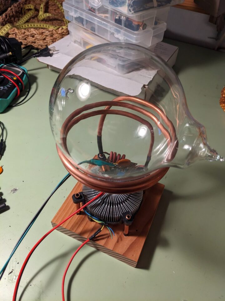
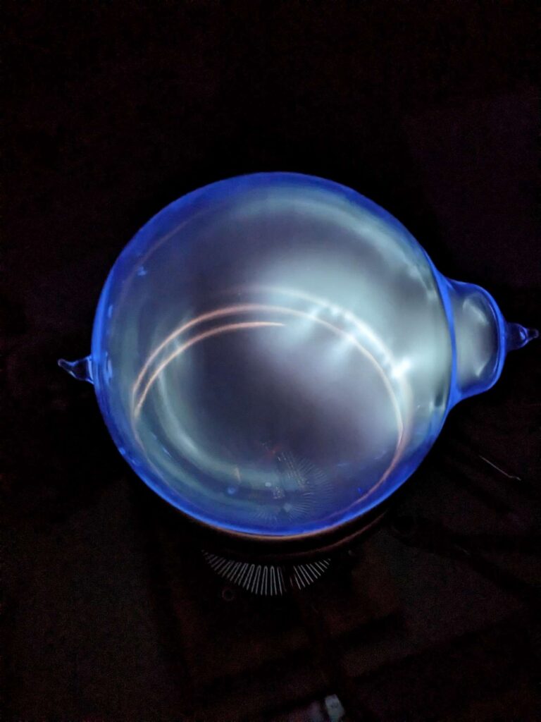
Plasma Toroid Lamp
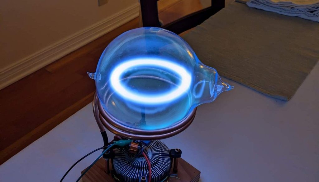
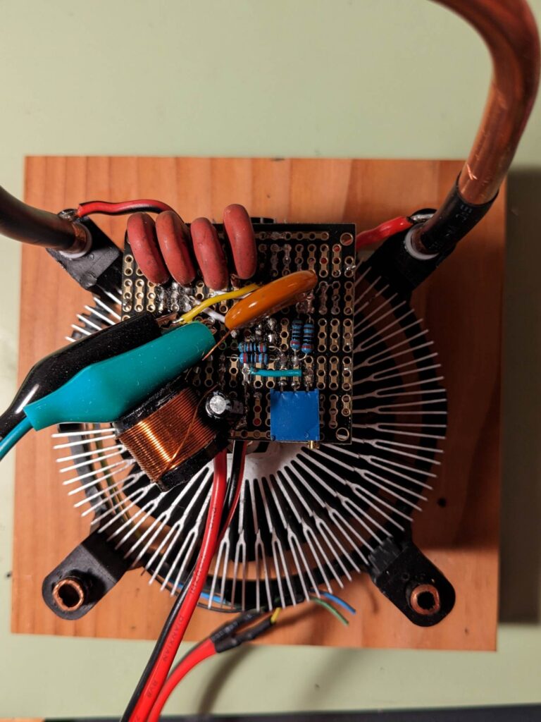
This is an implementation of a HFSSTC (High Frequency Solid State Tesla Coil) circuit. The key component is a high current(50A) MOSFET. This acts as a self-oscillating switch. The circuit parameters are tuned to create a 15MHz frequency at the primary coil. High voltage excites low pressure Xenon gas, and the precise frequency couples the plasma with the primary coil, creating an effective secondary coil that appears as a ring of plasma.
1.2MV Tesla Coil
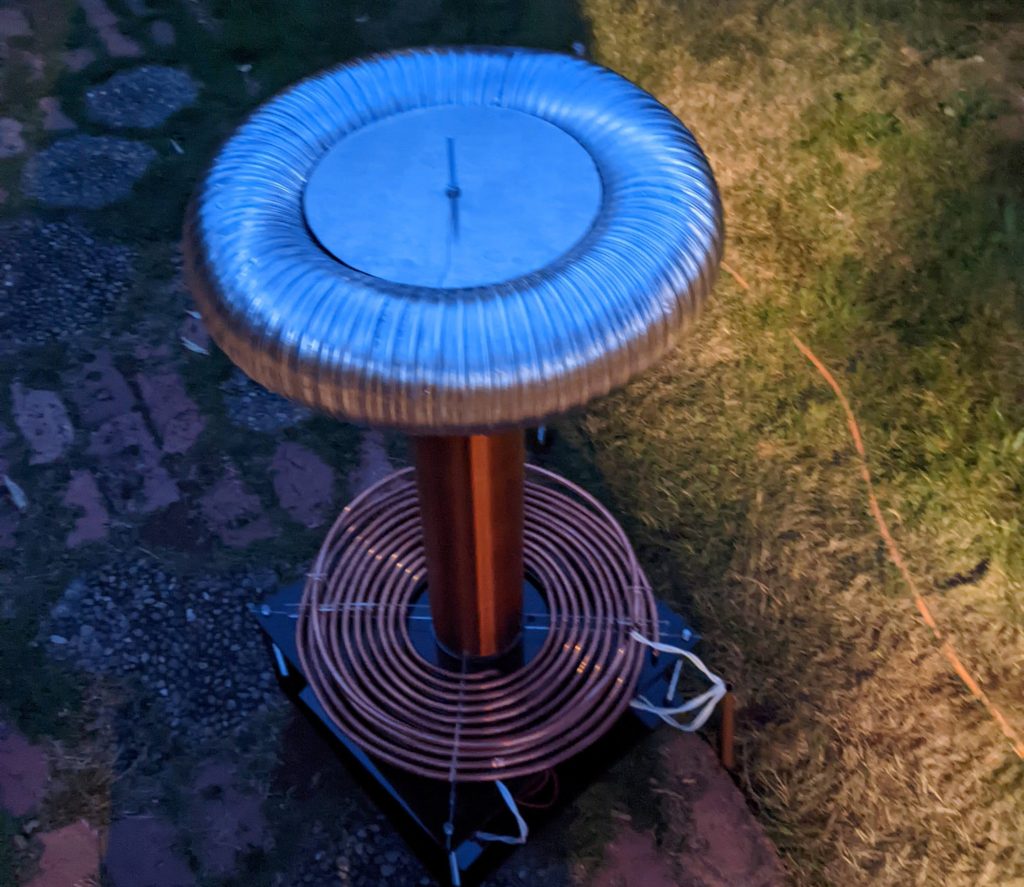
I designed and built this tesla coil from first principals, modeling the two coupled RLC systems as damped harmonic oscillators. Matching the resonant frequency of the secondary and primary coils is critical. The coupling coefficient between the two coils is a central design constraint that determines the maximum voltage possible. A low coefficient (<0.05) allows significant energy to be wasted in the primary coil, while a high coefficient (>0.2) allows energy to transfer too quickly, causing the spark gap to fire more frequently, and loose more energy doing so. I used Barton B. Anderson’s JavaTC program to tune the geometry of my Tesla coil for a coupling coefficient of ~0.1.
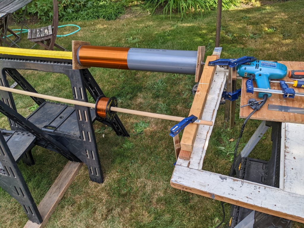
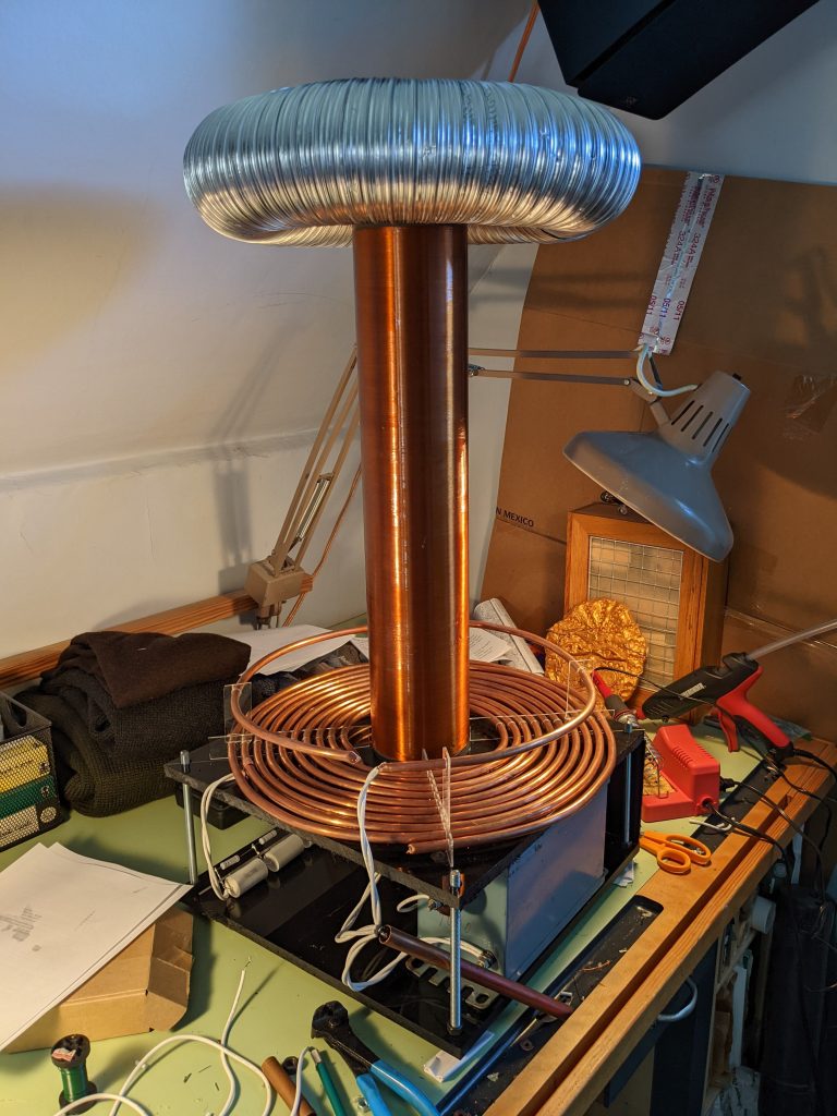
Some factors make the real world tesla coil behave differently from my model. One such factor is the capacitive loading of the spark gap itself. This is rather complicated to model, but can be accounted for by “detuning” the frequency of the primary coil. For this reason the hookup on one side of my primary inductor can be moved along the coil, allowing the inductance to be increased, accounting for the spark gap and empirically tuning for maximum performance.
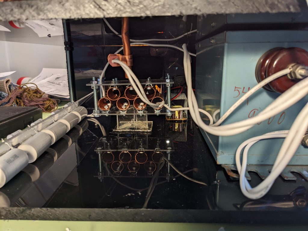
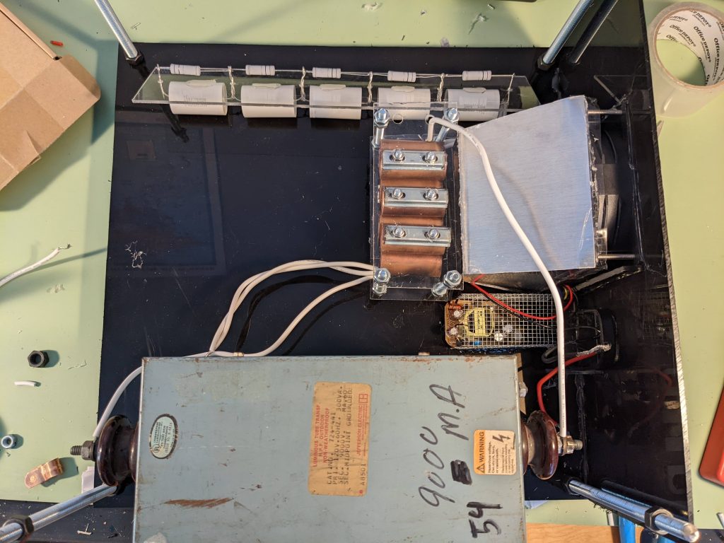
The spark gap itself also requires some tuning, as the exact voltage breakdown of the system is dependent on many environmental factors, including surface oxidation of the copper pipes used, and small changes in the spark gap width due to imprecise construction. Besides reducing erosion/wear of the spark gap, utilizing many smaller spark gaps allows me to adjust the voltage by using alligator clips to short one or more of the spark gaps. When starting the tesla coil for the first time, it is often necessary to short all but two of the spark gaps to break through oxidation buildup, before a more gaps can be opened to increase the voltage. In the future I would like to explore the design of a solid state switching mechanism, as it allows for more convenient tuning of the system.