ML camera tracker
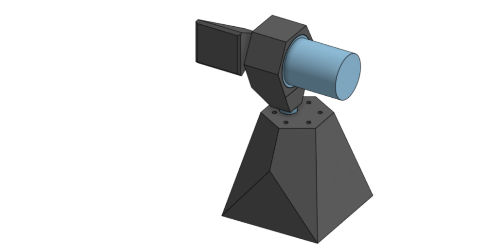
(IN PROGRESS) I’m working on a camera gimbal for tracking flying objects (and more) using computer vision. Applications include videography of RC aircraft projects and automated roommate targeting with a nerf gun.
My gimbal needs more precision/power than readily available/cheap servo or stepper motors can offer, so I’m designing a control system from scratch to control cheap DC gear motors. Robust control is enabled by two feedback mechanisms: high resolution hall effect encoders for relative position, and the computer vision defined object centroid for absolute angular position. The goal is for this device to be fully self contained using an Nvidia Jetson and lithium battery. I’m currently working on hardware integration, and starting code using the OpenCV library. Below is the Simulink model I built based off of the DC motor to tune PID parameters. The transfer function values were derived from a combination the gearmotor datasheet and testing with an RLC meter.
Bicopter
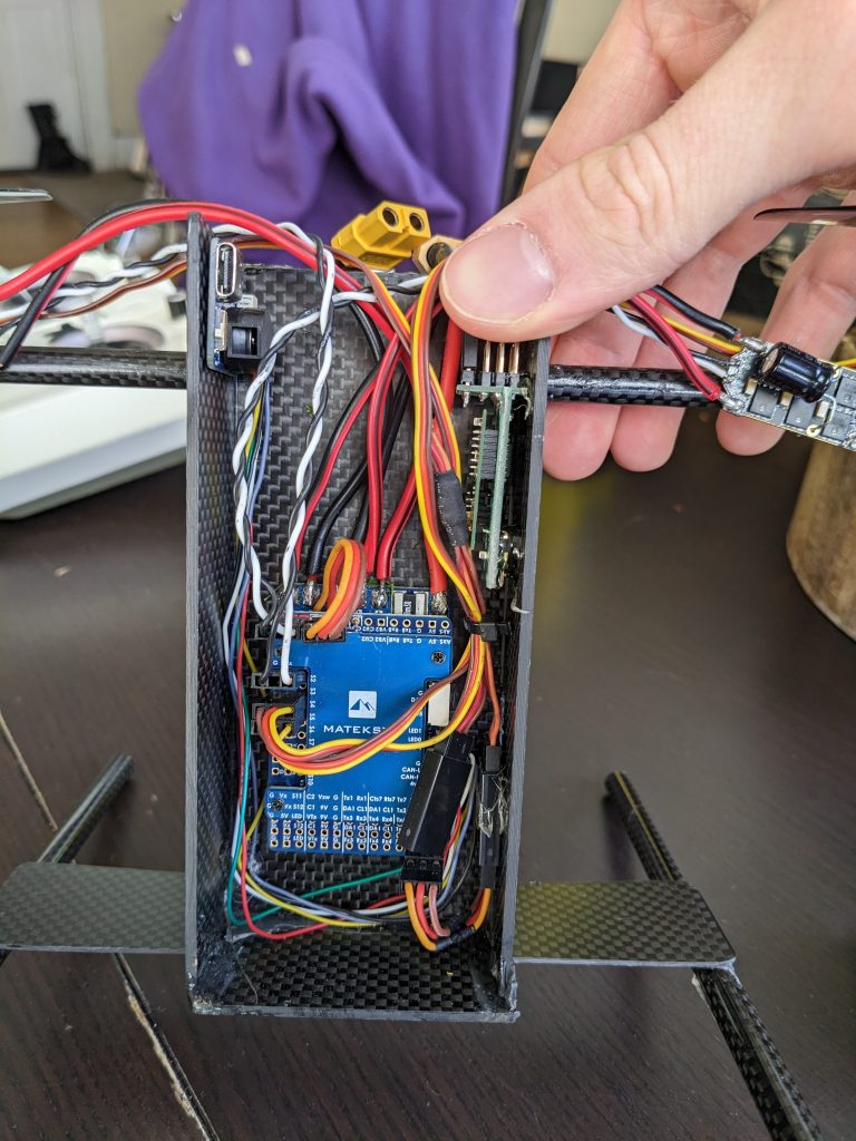
Two rotors, each actuated by a servo. STM32-based Flight Controller. PID closed loop control with FF. Very tricky to tune pitch axis since rotor tilt controls two degrees of freedom: both vehicle pitch and forward lateral movement. Tuned heuristically from approximated step responses derived from black-box logging.
Kindly ignore the mess of the random alleyway I’m flying in
Novel Hexacopter
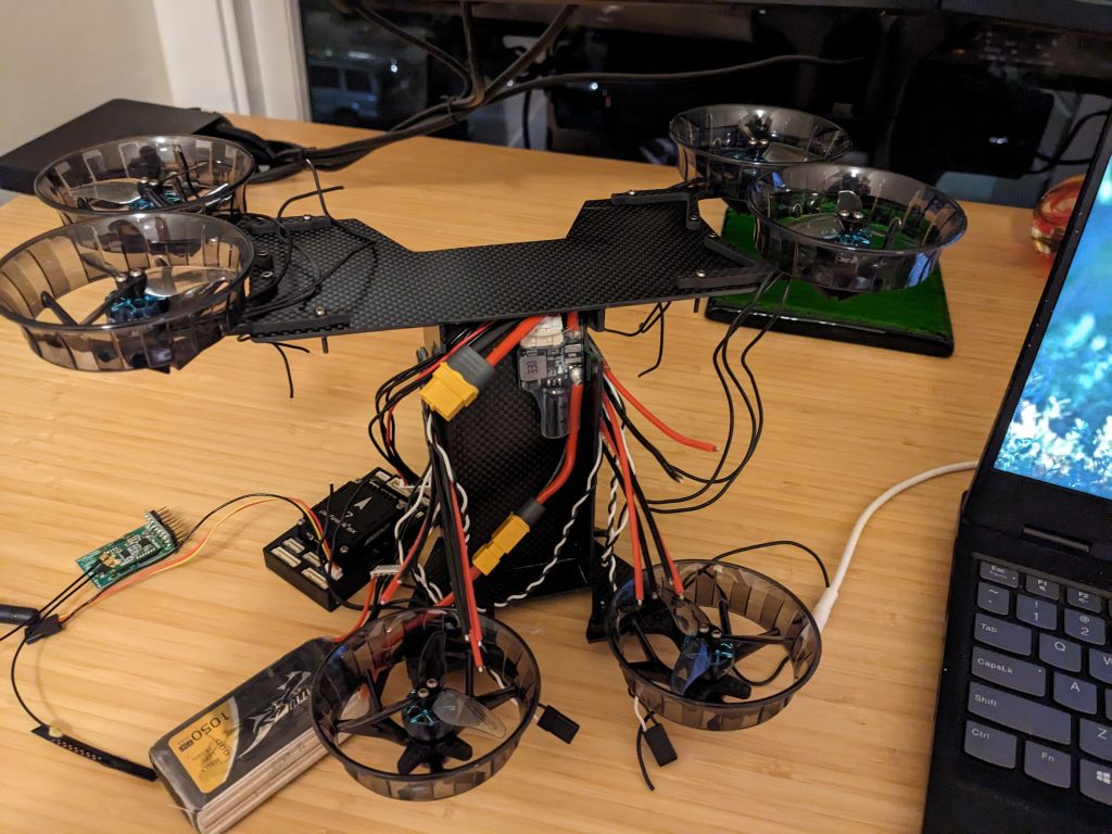
This hexacopter was built as a subscale demonstrator of an experimental rotor configuration for a professional role. I’ve posted it here as an example of my experience with PX4 firmware. This vehicle required a custom build of PX4 to define the actuator matrix in three dimensions due to the vertical separation of the rotors.
Colibri EVTOL
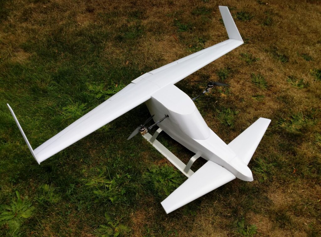
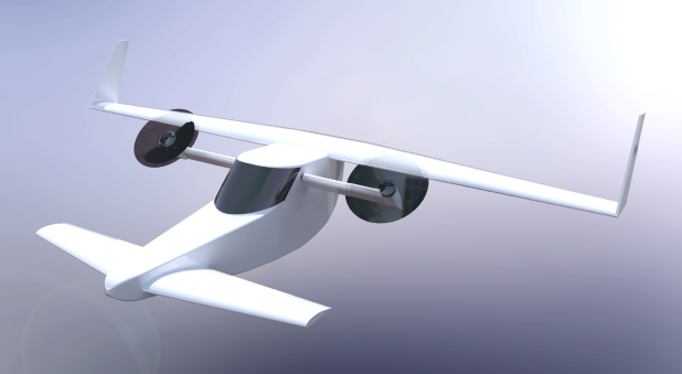
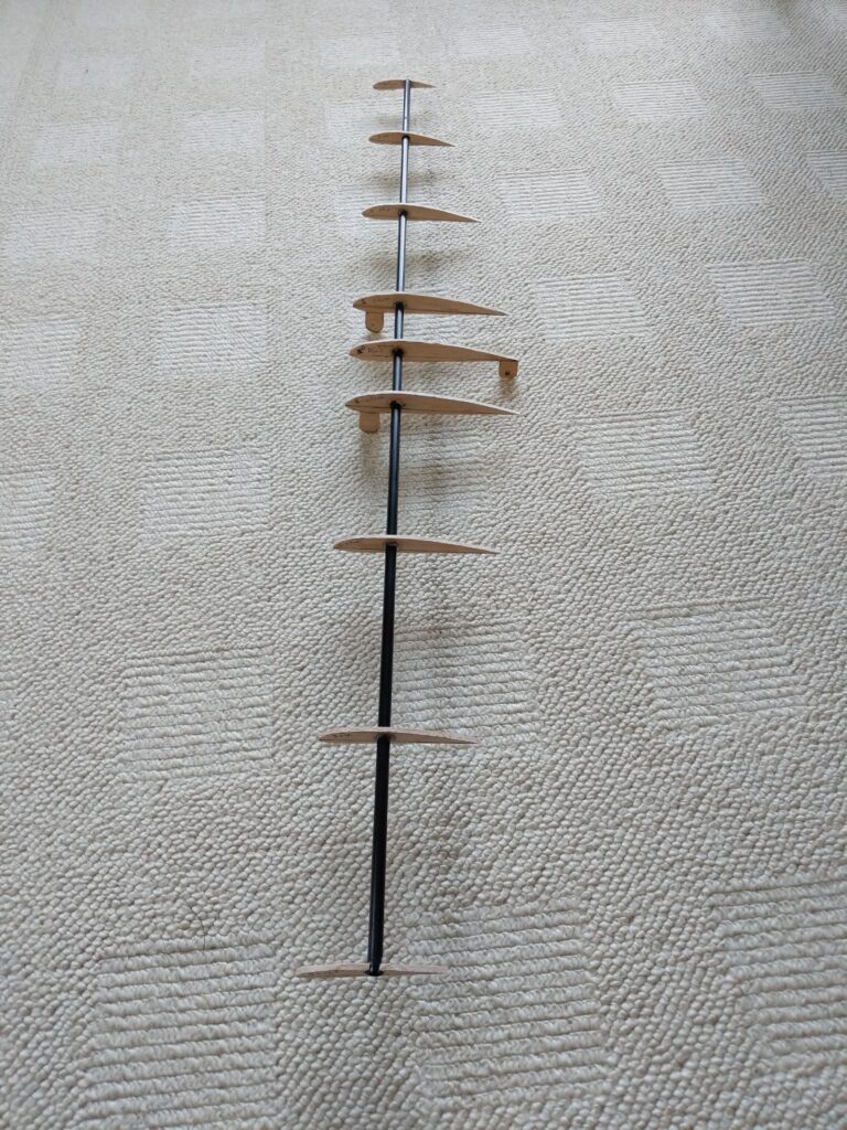
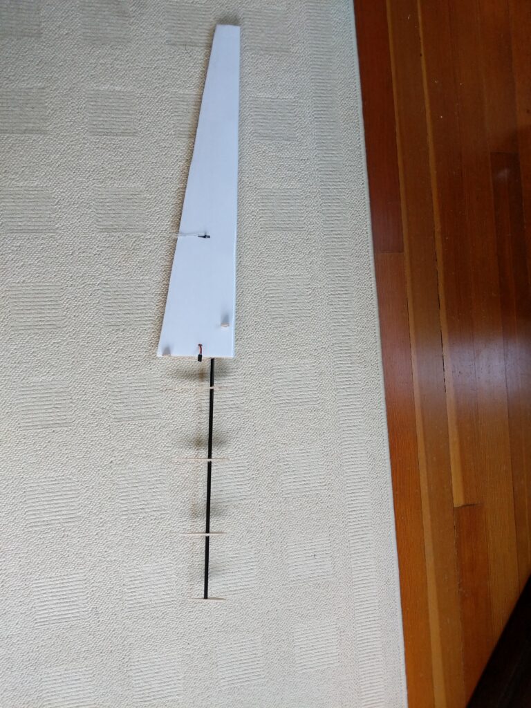
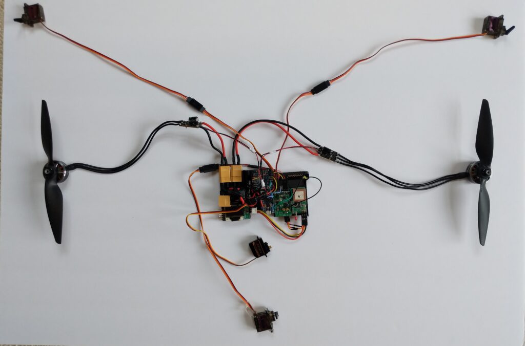
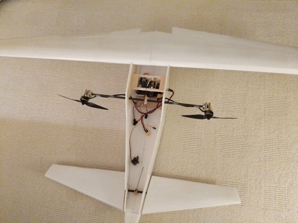
The project is the culmination of many years designing and building RC aircraft. Below is a summary of the project (Summer 2021):
Motivation
Improvements to battery and motor technology have pushed the electrification of small passenger aircraft into the realm of practicality. Inherent advantages of electric propulsion are being leveraged to design entirely new kinds of aircraft. Many startups hope to carve out their own niche, fulfilling the popular desire for flying cars with short range intercity multirotors. Other, more ambitious ventures hope to provide long range public transportation with hyper-efficient fixed wing concepts that can transition seamlessly between horizontal and vertical flight. These hybrids are posed to revolutionize transportation, competing directly with combustion fueled counterparts. The engineering challenges involved with creating this kind of jack-of-all-trades aircraft have produced a fascinating diversity of concepts. From Joby’s tilt-rotor hexacopter to Lilium’s ducted fan approach, there’s no shortage of startups pursuing this style of regional transport. But can their range be extended even farther? In the search for sustainable alternatives, how can we replace combustion-fueled interstate travel? Can electric propulsion power long-range transportation while still leveraging it’s aptitude for VTOL capabilities?
Goals
-Design an original concept for an interstate eVTOL aircraft
-Build a reasonably sized 1-2m foamboard airframe
-Build a powertrain using readily available quadcopter and model airplane electronics
-Use an Arduino and original code to achieve smooth transitions between flight modes and active stabilization in hover
-Achieve 20 mins of flight time with at least 2 mins of vertical flight on a 2100 mah 4s LiPo battery
Design Summary
Airframe
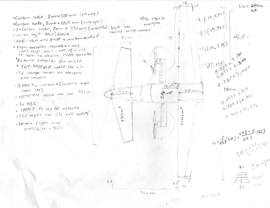
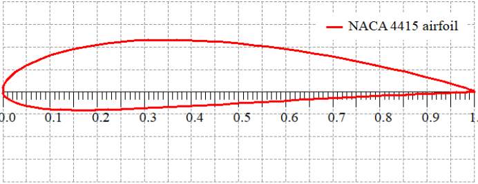
To achieve both horizontal and vertical flight I will use a tilt-rotor fixed wing layout. A fixed wing is a necessity for range as it offers the most efficient means of lift. The wing will feature a high aspect ratio and a roughly elliptical lift distribution. Both of these features are universal considerations maximizing the lift to drag ratio of a wing. To simplify the building process, the wing will have a mildly tapered trailing edge. When combined with a couple degrees of washout at the wingtips, the overall lift distribution will be nearly elliptical. This will change as the airplane approaches a stall. The washout will ensure that the center of the wing stalls first, allowing for a more gradual stall that preserves aileron authority longer.
To accommodate the tilt-rotors, the airframe will use an unconventional forward stabilizer as a canard. This differs from notable tilt-rotors like the V-22. The V-22 mounts tilt-rotors on either end of its wingtips. While this allows a more typical airframe, it adds considerable weight at the largest possible distance from the cg, and likely looses some lift in hover due to interference with the wing. The cg of a canard layout is naturally ahead of the leading edge, allowing for propellers and motors that are not only closer to the cg, but that also blow over a greater portion of the wing while in horizontal flight. This lends to the possibility of accelerated airflow over the wing at slow speeds, extending the flight envelope of the aircraft. Ultimately this allows for a smaller wing that produces less excess lift/drag while at higher speeds.
To accommodate the tilt-rotors, the airframe will use an unconventional forward stabilizer as a canard. This differs from notable tilt-rotors like the V-22. The V-22 mounts tilt-rotors on either end of its wingtips. While this allows a more typical airframe, it adds considerable weight at the largest possible distance from the cg, and likely looses some lift in hover due to interference with the wing. The cg of a canard layout is naturally ahead of the leading edge, allowing for propellers and motors that are not only closer to the cg, but that also blow over a greater portion of the wing while in horizontal flight. This lends to the possibility of accelerated airflow over the wing at slow speeds, extending the flight envelope of the aircraft. Ultimately this allows for a smaller wing that produces less excess lift/drag while at higher speeds.
It’s important to note that the V-22 suffers from problems inherent to tilt-rotors. It can neither effectively auto-rotate nor glide particularly well. This has contributed to the fatality of a number of crashes involving power loss. To avoid the hazards of associated with being neither a good helicopter nor airplane, my eVTOL concept will lean heavily towards fixed wing flight. Despite an undersized wing, safety necessitates slow speed flight and reasonable glide characteristics in the case of power failure. The wing uses a full length elevon in normal flight, but when transitioning, the canard will assume pitch control, allowing the elevon to deflect downwards as a flaperon. This intermediary flight mode offers a lower stall speed and increased drag, allowing for a slow speed horizontal landing in an emergency situation.
(note: the canard uses the same airfoil profile as the wing, so it is swept back to ensure it always stalls first)
This design decision eliminates the need for autorotation and collective pitch control. Additionally, the propellers will forgo any cyclic pitch control, lending themselves to the simplified layout of an electric powertrain. The same mechanism that tilts the rotors forward will control pitch in hover.

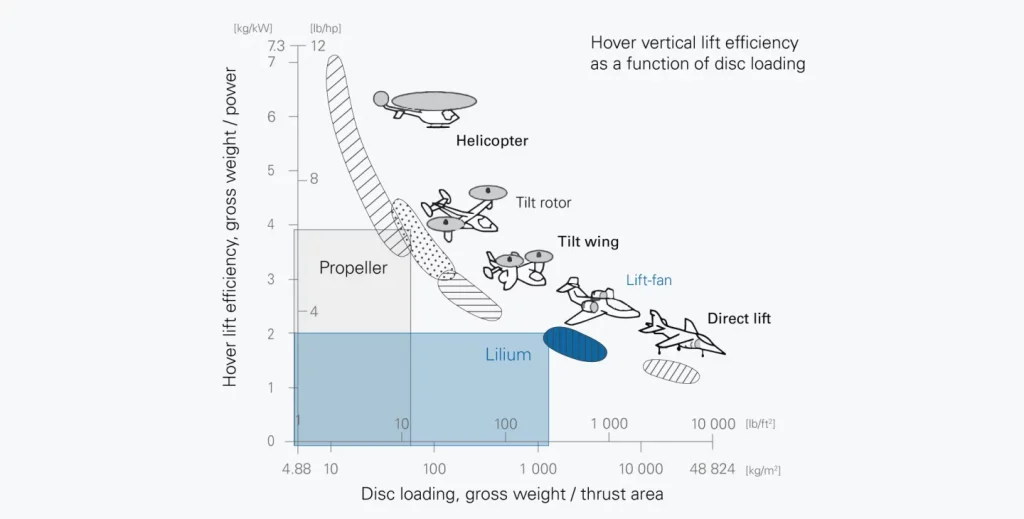
Disk loading is another tricky aspect of tilt-rotors. Helicopters place more demand on their rotors than those of an airplane propeller. To lower disk loading helicopters use large rotor blades. The problem becomes obvious when those blades must be tilted forward. The V-22 uses propellers that are as large as practicality allows, but this limits tip velocity, resulting in a slow cruise speed and inefficient, low-aspect ratio blades.
Fortunately efficiency in hover is of relatively little concern for a point to point transporter. Lilium recognized this with their regional eVTOL. They utilize 36 small lift fans for propulsion and lift, disregarding high disk loading in hover. This level of aerodynamic complexity is sure to cause some loss of efficiency in horizontal flight however. Ducted fans have the potential to improve efficiency by reducing tip losses, but this is typically given a similar diameter to a comparable propeller. As numerous as they are, Lilium’s fans have relatively little combined area compared to possible open-rotor design. Lilium’s angle on ducted fans includes quiet operation, a factor that again becomes less of a consideration with longer, higher-altitude flights and short hovers. My concept will utilize a pair of of high aspect ratio bi-propellers optimized for horizontal flight, sacrificing high disk loading and excessive blade pitch in hover.
Electronics
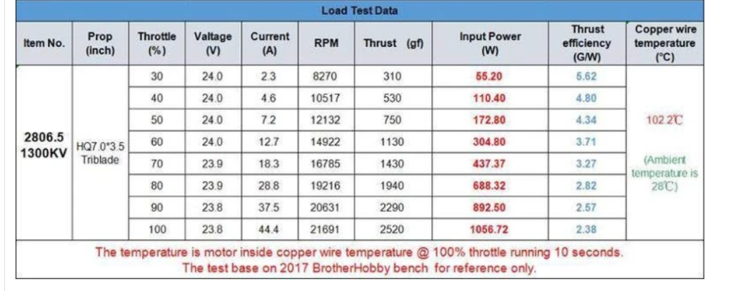
With only 14.8v and only a slightly more draggy prop, 2/3 should be a conservative estimate of the RPM I can expect. This is equal to 12,826rpm. Below is an excerpt from the manufacturer’s performance data on the propeller at 12000rpm. This indicates the aircraft will produce at least 4.5 pounds of thrust in a static hover. Given a margin for roll authority with differential thrust, this gives me a maximum possible weight for the total airframe. With a 2100mah battery I should be able to achieve a 20min flight time at an average of less than 40% throttle. 2100mAh/4.6A= .46 hours = 27.4 mins. Given that most of the flight (horizontal) will use significantly less throttle than what’s needed to hover, this should be achievable.
When selecting electronics for an RC aircraft I start with the battery. It characterizes the general weight and power of the aircraft. I’ll be using a 4s 2100mah Lithium Polymer battery. At 20mins of flight time this should allow somewhere around a 1/20th scale demonstrator. For an RC plane of this size I would typically use a three cell battery, but an extra 4.2 volts will be needed to hover. A pair of high performance race quad BLDC motors will spin the props. I choose the 2806.5 Avenger 1300Kv motors paired with an APC 8×4.5 Bi-Blade 8″. At 14.8v a 1300Kv will spin at around 19,000 rpm. Of course this is given no resistance which isn’t particularly useful. A look at the manufacturer’s load testing shows that at 24v and a 7×3.5 tri blade, the motor spins at about 2/3 of its theoretical Kv.
8x4.5MR                  (8x45MR.dat)                                 12/25/14


         ====== PERFORMANCE DATA (versus advance ratio and MPH) ======

         DEFINITIONS:
         J=V/nD (advance ratio)
         Ct=T/(rho * n**2 * D**4) (thrust coef.)
         Cp=P/(rho * n**3 * D**5) (power coef.)
         Pe=Ct*J/Cp (efficiency)
         V  (model speed in MPH)

 PROP RPM =      12000

         V          J           Pe         Ct          Cp          PWR         Torque      Thrust
       (mph)     (Adv Ratio)                                       (Hp)        (In-Lbf)     (Lbf)
         0.0        0.00      0.0000      0.1215      0.0494       0.225       1.181       2.283
         2.5        0.03      0.0669      0.1207      0.0503       0.229       1.204       2.267
         5.1        0.06      0.1302      0.1197      0.0513       0.234       1.227       2.249
         7.6        0.08      0.1900      0.1186      0.0522       0.238       1.249       2.228
        10.1        0.11      0.2465      0.1173      0.0531       0.242       1.270       2.204
        12.7        0.14      0.2997      0.1158      0.0539       0.245       1.289       2.176
        15.2        0.17      0.3498      0.1141      0.0546       0.249       1.305       2.143
        17.7        0.20      0.3968      0.1121      0.0551       0.251       1.319       2.106
        20.3        0.22      0.4410      0.1098      0.0555       0.253       1.328       2.062
        22.8        0.25      0.4825      0.1070      0.0557       0.254       1.331       2.010
        25.3        0.28      0.5214      0.1038      0.0555       0.253       1.328       1.950
        27.9        0.31      0.5578      0.1002      0.0551       0.251       1.318       1.883
        30.4        0.33      0.5915      0.0962      0.0544       0.248       1.302       1.808
        33.0        0.36      0.6228      0.0920      0.0535       0.244       1.281       1.728
        35.5        0.39      0.6518      0.0873      0.0523       0.238       1.252       1.641
        38.0        0.42      0.6783      0.0825      0.0509       0.232       1.217       1.550
        40.6        0.45      0.7023      0.0775      0.0492       0.224       1.178       1.456
        43.1        0.47      0.7238      0.0724      0.0474       0.216       1.134       1.359
        45.6        0.50      0.7430      0.0669      0.0452       0.206       1.081       1.257
        48.2        0.53      0.7591      0.0613      0.0428       0.195       1.024       1.152
        50.7        0.56      0.7725      0.0556      0.0401       0.183       0.960       1.044
        53.2        0.59      0.7828      0.0497      0.0372       0.169       0.890       0.934
        55.8        0.61      0.7886      0.0438      0.0341       0.155       0.815       0.823
        58.3        0.64      0.7899      0.0377      0.0306       0.140       0.733       0.709
        60.8        0.67      0.7853      0.0316      0.0269       0.123       0.644       0.594
        63.4        0.70      0.7704      0.0254      0.0230       0.105       0.550       0.477
        65.9        0.72      0.7366      0.0191      0.0188       0.086       0.450       0.359
        68.4        0.75      0.6645      0.0129      0.0146       0.066       0.349       0.242
        71.0        0.78      0.4869      0.0065      0.0104       0.047       0.249       0.122
        73.5        0.81     -0.0019      0.0000      0.0065       0.029       0.155       0.000
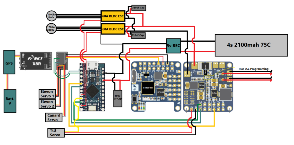
Power from the battery will be split between electronic speed controllers(ESCs) for the motors, a flight controller board, and a 5v BEC. The ESCs run an open source software called BL Heli. This is critical because I will be signaling the ESCs with raw PWM signal from the Arduino. Typically the ESC signal is bidirectional. This allows for RPM filtering with a standard flight controller. Without RPM filtering BL Heli allows me to tune the ESC for my specific motors. I wont go too much into motor tuning methodology because it’s widely applicable to quadcopters and nothing unique on this project. The motors spun best with a slightly higher timing angle (around 18 deg) and with medium demag compensation.
The flight controller (FC) allows access to the ESCs with it’s USB port. Most critically the FC also provides gyro data to the Arduino for the pitch and roll axis. It has a built in BEC as well, but with this many 5v outputs it wont be able to handle everything, hence the dedicated BEC. All the control surfaces will be handled by the receiver. It’s possible to drive the servos using the flight controller or the Arduino directly, but the receiver offers the most direct means of control. Its the “dumbest” electrical component, so if anything goes wrong with software in the Arduino or FC, I’ll still be able to glide to the ground. The RX also relays GPS and Battery telemetry to the transmitter.

Code
#include "PWM.hpp"
#include <Servo.h>
#include <Wire.h>


//output variables for motors and tilt
int leftmotor;
int rightmotor;
int tiltOUT;

//input variables from FC
int throttle;
int roll;
int pitch;
int yaw;
int tiltIN;

//intermediate variables for transitioning
int rollMIX;
int yawMIX;
int pitchMIX;


//Outputs
Servo leftmotoroutput;
Servo rightmotoroutput;
Servo tiltoutput;

//pins in
PWM ch1(0);
PWM ch2(2);
PWM ch3(3);
PWM ch4(7);
PWM ch5(1);


void setup () {

  ch1.begin(true);
  ch2.begin(true);
  ch3.begin(true);
  ch4.begin(true);
  ch5.begin(true);
  //Output Pins
  leftmotoroutput.attach(5);   // throttleleft
  rightmotoroutput.attach(9);  // throttleright
  tiltoutput.attach(6);      // tiltservo
}

void loop () {

  //making math easier  for mixing(setting the midpoint to zero)
    if (ch1.getValue() > 1000 && ch1.getValue() < 2000) {
    throttle = ch1.getValue() - 1500;
  } else {
    throttle = -500;
  }

  tiltIN = ch5.getValue() - 1500;
  roll = ch2.getValue() - 1500;
  pitch = ch3.getValue() - 1500;
  yaw = ch4.getValue() - 1500;


  //transitions
  tiltIN = constrain(tiltIN, -500, 500);
  //reduces roll and pitch as motors tilt forward, while introducing yaw
  rollMIX = roll * (1 - ((tiltIN + 500) * 0.001));
  yawMIX = yaw * ((tiltIN + 500) * 0.001);
  pitchMIX = pitch * (1 - ((tiltIN + 500) * 0.001));
  //adding the axis together for throttle values
  leftmotor = throttle + (rollMIX * 0.2) - (yawMIX * 0.2) + 1500;
  rightmotor = throttle - (rollMIX * 0.2) + (yawMIX * 0.2) + 1500;
  tiltOUT = - tiltIN - pitchMIX + 1500;
  //PWM ranges
  tiltOUT = constrain(tiltOUT, 1200, 1800);
  leftmotor = constrain(leftmotor, 1000, 2000);
  rightmotor = constrain(rightmotor, 1000, 2000);
  //outputs
  tiltoutput.writeMicroseconds(tiltOUT);
  leftmotoroutput.writeMicroseconds(leftmotor);
  rightmotoroutput.writeMicroseconds(rightmotor);

  delay(30);
}
This code switches between inputs as the rotors transition. While hovering differential thrust is used for stabilized roll and the tilt servo for stabilized pitch. As the blades pitch forward the combined PID and control input from these axis is reduced. Simultaneously, yaw input replaces roll input in differential thrust. The yaw has no PID stabilization as the aircraft is passively stable with its vertical stabilizers. The transmitter itself has a simple Lua script that temporarily raises the angle of incidence of the canard during transitions.

Without active stabilization, a hovering multirotor has neutral static stability. It may fly for a few seconds but it will be nearly impossible to keep in the air, let alone go where the pilot wants. Active stabilization assists the pilot. I will be implementing a basic control loop, known as a PID loop. A PID loop has proportional, integral and differential components. Each part is a “loop” meaning it continually reacts to inputs that are influenced by its own outputs as well as outside disturbances and pilot inputs. A PID loop will be assigned to the pitch and roll axis. Below is the bare-bones equation:

//basic PID math
unsigned long past;
double kp, ki, kd;
double In, Out, Setpoint;
double errorSum, pastError;

void Compute()
{
   unsigned long now = millis();
   double timeChange = (double)(now - past);
   double error = Setpoint - In;
   errorSum += (error * timeChange);
   double dErr = (error - pastError) / timeChange;
   Out = kp * error + ki * errorSum + kd * dErr;
   pastError = error;
   past = now;
}
The purpose of the PID loop is to continually output an error value, in this case the difference between a given setpoint(or pilot input) and data from the gyro. The proportional term looks at the angle of the aircraft in a given axis, allowing for motor inputs that move the aircraft towards the setpoint. The derivative term looks at angular velocity. This allows for dampening of angular momentum. As the P term moves the aircraft towards the setpoint, the D term will grow stronger in opposition, eliminating oscillation. The integral term looks at the angle over time, growing in strength over the course of continuous disturbances like wind or imbalances in the aircraft. Key additions to the basic PID include feed-forward and auto leveling. Feed-forward reduces the authority of the PID loop, prioritizing pilot inputs to a given degree. Auto-leveling acts as a proportional filter to pilot inputs, influencing the setpoint so that the aircraft is “attracted” towards level. The key challenge is to tune the strength of these additions and the respective PID loops for each axis.